This article provides a comprehensive breakdown of the A20112 power supply architecture, its core components, operational stages, and common troubleshooting methodologies. Overview of the A20112 Power Supply Architecture
The A20112 is a classic linear-regulated (or in some variants, a hybrid switching-to-linear) power supply architecture. It is designed primarily for applications that require low electromagnetic interference (EMI), ultra-low output ripple, and robust tight regulation. Key Technical Specifications
A typical power supply following this architecture is designed to transform raw electrical energy into a stable output suitable for sensitive electronic devices. Most DC power supply circuits, including the A20112, rely on several key stages:
The Renesas is a Continuous Conduction Mode (CCM) PFC controller IC designed to improve power efficiency and reduce harmonics in AC/DC power supplies. Application: PFC controller (CRM/CCM). Package: Usually 16-pin SOP (16SOP).
If the voltage is correct at idle but drops significantly under load, the active regulation components are likely failing or overheating due to degraded thermal paste on their heatsinks. Safety and Best Practices
Maintains high power factor by regulating the input voltage and current to be in phase, reducing power loss. 2. Key Components of the A20112 Power Supply Schematic
Look for scorched PCB traces around the power pass transistors and high-wattage resistors. Check the continuity of the main input fuse. Step 2: Check Primary and Secondary AC Voltages
The part number belongs to a power supply from Macrolink, Inc., used in aircraft (often misspelled as "Aircra" in databases).
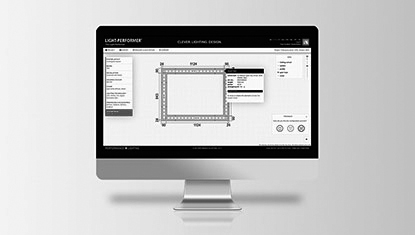
PCB layout tips (practical, high impact)
Typically configured for standard mains (110V/220V AC) or a high-voltage DC intermediate stage.
This paper presents a comprehensive design, schematic, component selection, analysis, and implementation guide for the A20112 power supply. It covers functional requirements, block diagrams, detailed circuit schematics, component specifications, PCB layout considerations, thermal and EMI analysis, testing procedures, and a bill of materials (BOM). Assumptions: A20112 denotes a hypothetical single-output DC power supply delivering 12 V at up to 2 A (12 V/2 A) with both short-circuit protection and moderate line/load regulation; use-case is general-purpose bench or embedded-power application. Adjust ratings and safety standards to your exact A20112 specification if different.
Insert a low-value sense resistor on the output return path and use an op-amp to feed back into the optocoupler. Refer to the schematic’s primary-side current sensing as a model.
Test the main bridge rectifier diodes and any feedback Zener diodes using your multimeter’s diode check function.
In most cases, detailed circuit diagrams for such components are classified or proprietary.
that need a "set it and forget it" power source that won't interfere with sensitive signals.
The R2A20112 is designed by Renesas to improve efficiency and reduce noise in power supply designs. Its schematic footprint typically includes: